
Making the Complex Simple
Accurate measurements are made not only by using the right equipment, but also employing the right practices. The software environment dynamically builds VNA, spectrum analyzer, and power meter functionality from the instrument configuration and resource interconnections. Combined with a code base of over 30 years of microwave test and measurement experience, Cassini delivers streamlined multi-instrument test in a simple, more powerful test work flow. This expert system software enables a user to design and execute sophisticated microwave measurements accurately and reliably every time.
- Simple Graphical Programming Environment
- User Access Permissions Provides Control
- Bench-like Instrument Control During Development & Debugging
- Advanced Datalog and Graphing Tools
- Offline test development through Virtualization
- Learn More »
- Learn More »

Unleash State Machine Speed
Under the surface of the graphical programming environment is a fundamentally different interaction of software and hardware. Test programs are compiled into a dedicated, run-time state machine on FPGAs that drive the instrumentation and signal processing in real time. This produces faster tests, consistent measurements, and enables a powerful feature never before possible in an ATE system - intelligent test optimization. Built into the compiler is Synapse, a test state optimizer that guarantees the most efficient program execution on any tester configuration.
-
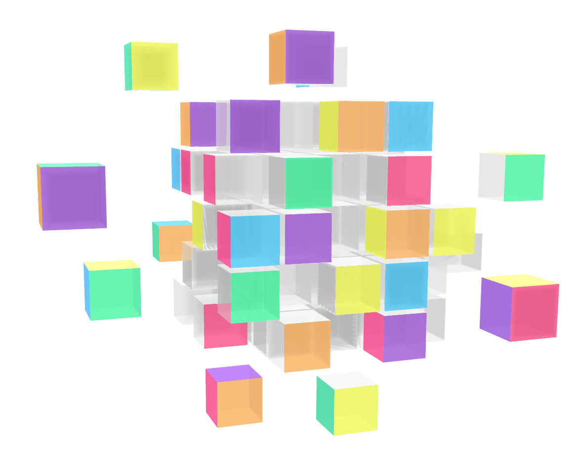
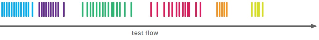
 Typical test programs are designed with an execution order that follows the programmer’s code
organization. While conventional, this can have unintended inefficiencies — redundant program calls,
unnecessary instrument settings, and repeated test states. Code optimization and reuse across different
devices requirements and tester configurations can quickly become unmanageable.
Typical test programs are designed with an execution order that follows the programmer’s code
organization. While conventional, this can have unintended inefficiencies — redundant program calls,
unnecessary instrument settings, and repeated test states. Code optimization and reuse across different
devices requirements and tester configurations can quickly become unmanageable.
-
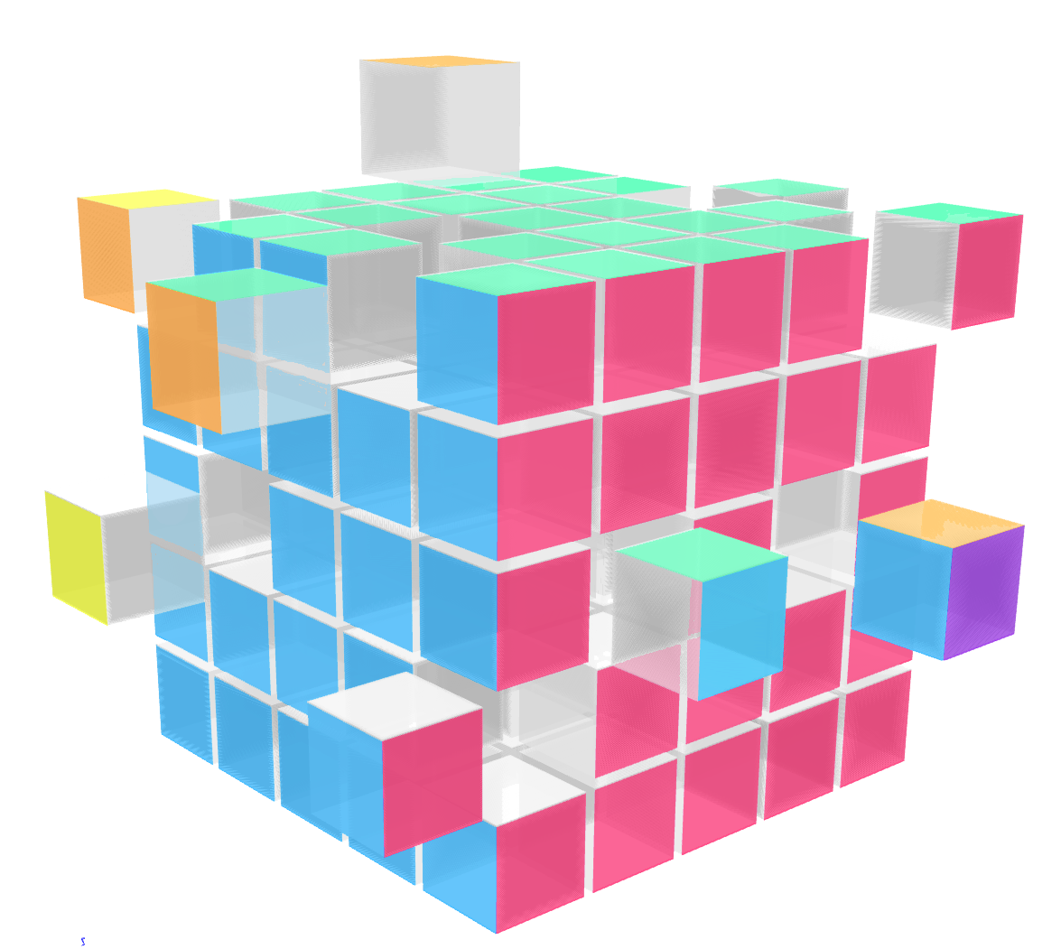
 Synapse optimizes test execution using an advanced state analysis of measurement setup and program flow.
This removes superfluous test states, groups similar types, executes repeated measurement setups in
parallel, and organizes the overall test flow to reduce processing and execution overhead.
Synapse optimizes test execution using an advanced state analysis of measurement setup and program flow.
This removes superfluous test states, groups similar types, executes repeated measurement setups in
parallel, and organizes the overall test flow to reduce processing and execution overhead.
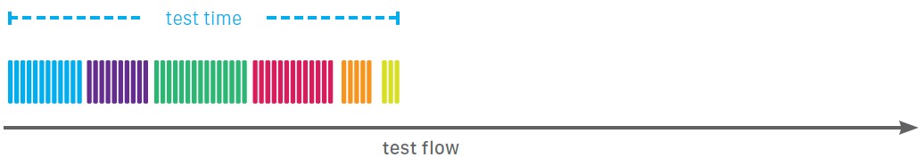 The result is a test program that is twice as fast (Typical test time improvement) and guarantees the
most efficient execution on any Cassini instrument and tester configuration. With full user control over
where and how Synapse optimizes the test program, the focus can be put back on test and measurement
design.
The result is a test program that is twice as fast (Typical test time improvement) and guarantees the
most efficient execution on any Cassini instrument and tester configuration. With full user control over
where and how Synapse optimizes the test program, the focus can be put back on test and measurement
design.
Building Bridges to Islands of Automation

Guru is the first of its kind, integrating the file system with a database and networking backbone to create a seamless software work flow. With an integrated local and network storage architecture, Guru manages file directories, tester configuration resources, and storage space automatically across the entire production floor. Users can create tests and link resources while Guru keeps track of dependencies and distribution for easy organization and quick deployment to production with a host of powerful features.
- Digitally signs and encrypts files for reliable data transfer
- Rich Interactive Test Database (RITdb) and STDFv4 Support
- Link test resources with user-defined tags
- Versioning file system keeps a complete test development history
- File and data redundancy with automated backups
- Search, filter, and organize files quickly and efficiently
- Learn More »
- Learn More »
RI System Software
Cassini
- Real Time Measurements
- Guru Apps & Data
- Graphical Development Environment
- Measurement Expert System
- Synapse™ Test Plan Optimizer
- Regular Software Updates
- Effortless Data Collection
- Touch UI option for Production
Desktop
Offline Development
- Simulated Instruments
- Guru Apps & Data
- Graphical Development Environment
- Measurement Expert System
- Synapse™ Test Plan Optimizer
- Regular Software Updates
- Effortless Data Collection
- 4K Resolution for Development
Network Appliance
- Simulated Instruments
- Guru Apps & Data
- Graphical Development Environment
- Measurement Expert System
- Synapse™ Test Plan Optimizer
- Regular Software Updates
- Effortless Data Collection
- Up to 8 Simultaneous Workstations
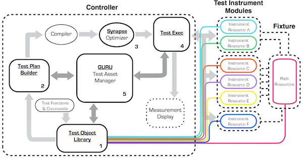
Software Architecture
From its inception Roos Instruments designed Cassini to have a more comprehensive interaction between ATE hardware and software. We found the best results by using a state-based approach in our software; it allows the software's commands to operate on the hardware components as state-based objects. It becomes easier to develop test plans and measurement algorithms when the programming interface reflects the changes in hardware states that occur during a test. The following section explains our approach to ATE software and how to use it to build measurements, create test plans, and control the flow of test execution.
Rapid Development
Simple, reliable test hardware driven by novel system software sets the RI tester apart from the competition. Designed to make fundamental measurements, the system hardware is tailored for speed, reliability and stability. Typical time-wasters such as redundant measurement states, error correction calculations, and instrument processing delays are reduced or eliminated through sophisticated automatic test plan optimization. Complex measurements are synthesized by the system software from the fundamental measurements taken at very high speed, woven together with the data processing to create error corrected data. With little effect on system speed, the measurements are unobtrusively captured and saved by the built-in database. RI's virtual instrument design provides superior performance at lower cost and high reliability.
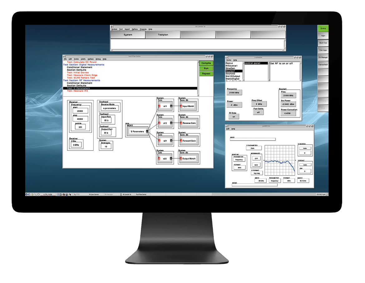
Graphical Test Plan Creation Tools
Test plan development plays a crucial role in the time-to-market equation. RI software provides the tools that enable engineers to quickly and easily debug tests, revise test programs, document, and analyze test data. Test plan creation is fast and intuitive with a graphical test plan editor. Just cut and paste tests as dictated by your requirements. RI systems allow your test engineers to design in a completely new and highly productive way. Operating in a multitasking graphical environment, test designers use a mouse to manipulate graphical objects (buttons) representing measurement processes, parameters and test results. Buttons are connected graphically and parameter values are set, resulting in a simplified flow chart-like picture of the test. Completed tests are stored in graphic form and are easily recalled and modified to create new tests.
Measurement Expert System
An ATE system needs both the right instruments and streamlined processes in order to deliver consistent results. This is especially true when production testing requires a durable DUT interface, consistency across multiple testers, and fast test times. Cassini integrates 80 collective years of microwave expertise into its workflow. Our expertise translates into accurate measurements, robust hardware, and a simplified user experience.
Optimization Ensures Maximum Performance
RI's test plan compiler and optimizer automatically considers time requirements for system state changes, identifies duplicate measurement states, and restructures the test sequence for highest measurement speed. Execution speed is improved dramatically by compiling and optimizing the test plan instead of simply interpreting it. Rapid test plan development makes device characterization a powerful capability of the RI system. The software allows you to change frequency ranges and add measurement mains with simple mouse selections. For example, adding multiple bias mains to a gain vs. frequency test requires adding a single DC bias state button. The large volumes of data generated by device characterization are collected, stored and analyzed by RI's built-in database. Debugging features including break mains and single stepping that help the user to quickly finish test plans.
Effortless Data Collection
Whether characterizing a part with hundreds of parameters or performing production testing with only a few parameters, capturing and storing measurement data is effortless with the integrated RI database. Test plans automatically store all system state, user and device information as standard data types in an SQL relational database. RI's Advanced Analysis Package allows you to analyze, summarize and view data, or export it to a variety of database and spread sheet formats.
Scalable User Interface
Log-on and security features of the RI software automatically tailor the user interface to fit the various requirements of the current user. System operators can easily select tests and start and stop the tester with a click of the mouse. Technicians can view real-time graphical test results to monitor fixture performance and overall lot/sublot performance. Production test engineers maintain complete control over tests and data. At RI, we recognize the unique requirements of each customer. We are prepared to work with customers to modify the interfaces to match specific production test environments. We also modify our data export formats to support existing data collection systems.
Revolutionary New Data Standard
Rich Interactive Test Database (RITdb) is a new datalog streadming and container format for storing and analysing testdata. Cassini systems natively support RITdb.
Learn More »Learn More about Device Interface »