

To exchange quickly, see ![]() Exchange Checklist for RI8574 System Controller ArcaOS EPC TIM.
Exchange Checklist for RI8574 System Controller ArcaOS EPC TIM.
Cassini System Controller should be removed while the system is powered down and the Fixture removed, TIMs can be left in place. If the system controller has failed, you will not need to follow the procedure to properly shutdown the system controller, skip to the next section. If a Fixture is still docked to the Test Head, remove it before starting the replacement process. The Guru ID and system serial number should not be affected by EPC exchange. Sites with high MTBF requirements should take advantage of the benefits that a on-site spare RI8574 provides.
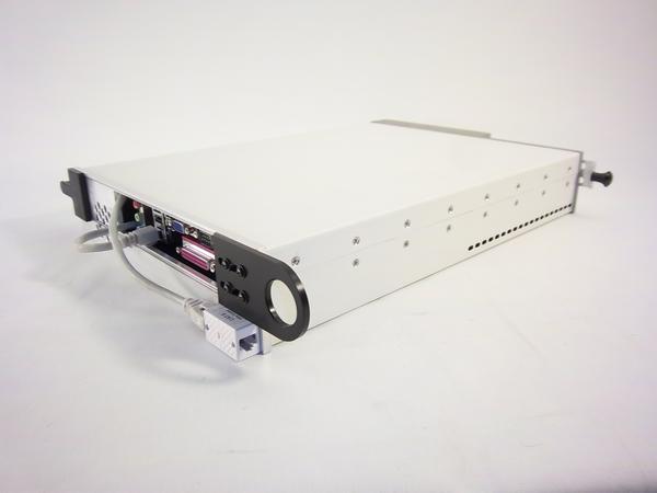
System Controller Test Instrument Module (TIM)
As with all Cassini TIMs, the System Controller, an "embedded PC" or EPC, was not designed to be serviced in the field, instead it can be replaced with a functional spare in minutes vs hours required to replace a failed component and risk of damaging sensitive internal instrumentation (RIFL 10MHz reference clock). The standard components are selected to work with the embedded OS and we have found that replacing equipment in the field usually adds to the complexity of the repair, reduces chances of success, and increases downtime. All components are chosen with enterprise class reliability with very high MTBFs and long warranty. If a Hard Drive or CPU fails, the entire system should be replaced. We have experienced a number of disk image tools miss critical disk partition information due to the type of file system, JFS, a reliable and fragmentation free used by other modern platforms.
Site Preparation
Sites using ShortCuts that include necessary patches and Guru Server v72 (June-2015) or greater do not require any preparation because the Guru ID is stored in the multiple RIFL Hubs in the Testhead and can be changed with a menu command instead of manually loading a Guru ID.
For using an older version of Cassini and Guru Server, the Spare EPC TIM can be initialized by the factory or done "just in time" after replacing an existing EPC with a USB Guru Key. The Guru ID dongle is used to identify the new hardware and quickly restore the entire environment from the Guru Server. Customers with only one system per location do not require USB Guru ID. A Guru ID USB drive may be provided with the spare System Controller. The USB Guru Key is issued by RI at the time the spare is ordered. Roos Instruments highly recommends having a spare system controller on-site for the fastest failure recovery. A single USB key contains the Guru IDs of all the systems on site, when more systems are added, the USB Guru Key can be updated. First prepare the key by unzipping the appropriate Guru ID to the root of the USB drive. Then load the USB Guru Key onto the system controller before Guru starts. Spare system controllers can also be configured as a dedicated replacement at the factory prior to shipping. Site custom network settings and Guru Address book entries may also be added prior to shipment, only if specifically requested. When ordering a spare system controller, specify the network settings and address book entries (if any) that should be loaded on the drive prior to shipment. If more than one Cassini system is deployed at a site, a special USB Guru Key can be used to identify the replacement System Controller. A single key can be used to identify any of the deployed Cassini systems by modifying the file structure to select the desired system. Detailed instructions are included with the USB Guru Key. This process is subject to change depending on the Guru Server version.
IMPORTANT: Every system controller includes a factory calibrated 10 MHz reference clock. The calibration (offset) is included on the disk image. Using another systems disk image may skew the 10 MHz reference clock data and may cause testplans to fail. DO NOT use traditional disk image tools to backup or restore the system controller OS. Replacement system controllers from the factory will be configured properly, otherwise the "C:\RI\RiflMasterDef.cff" or "d:\offset.txt" file has the offset value stored in it. Otherwise, follow the procedure for Calibrating 10 MHz reference offset.
Exchange Procedure
1. Shutdown the System Controller (only if running)
Always remove the Test Fixture form the Test Head prior to starting up the system. You can safely shut down the system with the Fixture attached, but you MUST remove the fixture before starting up the test system to prevent any possible damage to the Fixture and DUT interface following the standard "RI System Software Shut Down Procedure" covered in a previous step. If a Fixture is attached, remove the Fixture before powering down and removing the System Controller.
If the system controller is still running, close the RI System Software and shut down the OS. On the RI Message Window click with the left mouse button on the System pull down menu and then select Quit. The system will confirm with a dialog box that asks, "Are you sure you want to shut down the system?" Click YES and the RI system software will do some file maintenance and close, leaving the eCS desktop with the image of the RI Test Head. Now perform an OS shutdown by clicking on the Shutdown Icon (
2. Remove System Controller (EPC) TIM
For RI8574 Cassini 16 Infrastructure,
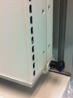
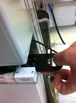
Carefully unplug the keyboard, mouse, monitor, network, any additional cables and (if provided) remove the "Guru ID" USB dongle. Simply pull the knob at the bottom of the System Controller to prepare it for removal. Remove the module by securely grabbing the side, then pulling the upper handle to release it from the docking interface.
For Small and Large Cassini EPC (RI8551), the System Controller is mounted inside the Infrastructure rack. Locate the system controller by opening the back door, disconnect the USB dongle, keyboard, mouse, monitor, network and any additional cables and cables and slide the system controller out of the rack.
3. Add Replacement System Controller (EPC) TIM
Attach keyboard, mouse, monitor, network, any additional cables and the Guru ID USB dongle (if provided) before installing the replacement System Controller. Once the cables are secure, slide the System Controller with cables up into the infrastructure cavity and then slide the System Controller into the slot until you hear a click. Then push in the bottom handle to lock the System Controller in place, steady force may be necessary.
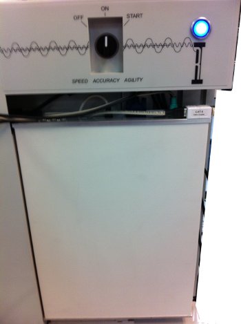
Turn the top panel switch to START, then release to ON position to start the new system controller.
4. Update Guru ID (Optional)
If the Guru ID does not match the system's Serial Number label, the Guru ID must be updated from the Infrastructure or .ZIP file. The Guru ID may need to be updated if it is not pre-configured for the system by the factory or the version of Guru is not greater than v71 and the Short Cut does not include the necessary Cassini patches. The Guru ID is displayed in the Logon (Guru > Logon) dialog prompt, "Please enter the Guru password for XXXXXXX", where XXXXXX is the Guru ID and System Serial Number. The Guru version number is after "RI Guru Server - GB83SB2A - XX.y" where XX.y is the version of Guru.
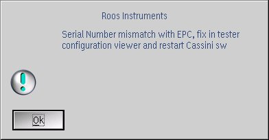
To update the Guru ID from the Infrastructure and migrate the 10 MHz RIFL calibration launch the Cassini application and a "Serial Number mismatch" prompt may appear (with Cassini v19 and Guru Server v72 or greater). Choose System > Tester from the Cassini main window, then choose Tester > Change EPC SerialNumber. Close Cassini main window and restart Guru by selecting System > Shutdown. Check the Guru Server version by looking at the Window list (CTRL+Esc or by pressing both the left and right mouse button at the same time on the Desktop)
To update the Guru ID from a .ZIP file (prior to Cassini v19 and Guru Server v72), the Guru ID should be updated via .zip files that contain the keys for each system (contact [email protected]). Unzip the correct system serial number to the root of the USB drive or D:/RiGuru/GuruKey folder and restart Guru (System > Shutdown) and it will automatically use the new Guru ID.
5. Configure Network and Guru Address Book
Any network TCP/IP settings (default DHCP), host name, network drive mounts, VNC settings, CUPS Printers or other OS customization must be performed.
If static IP or Hostname change is required, access the TCP/IP Configuration workbook from the System Setup (red toolbox taskbar icon) > Network > TCP/IP > TCP/IP Configuration. (See Configure TCP/IP Settings and Change Hostname in ArcaOS)
Shared network folders are accessed from Desktop > Local Network > File and Directory Connections (Samba). (See Connecting a Shared Network Folder (Samba))
VNC settings are Desktop > Programs > Installed Software > PM VNC Server > PM VNC Server. (note: copy the server icon to the Startup folder to automatically start VNC on reboot) (See Remote Access System Controller EPC with VNC)
If the Guru Server auto-detect feature is not being used (SLP, not on the same subnet), then address book entries need to be loaded from a backup (.gzp) or manually entered. Login > Apps > Guru Address Book Admin > Create New Connection > [IP or Hostname] > Type = Update > Save, Then System > Shutdown to restart Guru. For more details, see Connect to Guru Server with the Guru Address Book.
Confirm the Guru connection when the Guru "System" or "Logon" button appears green, indicating the Guru Server is found and that updates are being retrieved.
6. Sync Guru Objects
Backup all objects to the Guru Server, use the Sync Util to send hardware definitions (drivers) to the Guru Server by choosing Apps > Sync Util. Select the Guru Server name entry (added with the Guru Address Book in step 5) next to Guru B and press Connect Gurus button. Now press Sync Up (Update Guru B from Guru A) to copy any guru objects not yet on the server.
7. (Optional) Configure ELO Touch Display. Follow the