Debug Setup:
1.
The fixture should be configured as shown in Figure 1. This allows easy access to the RF, static digital, and other pins attached to the DIB. Install it onto the test head and activate the software fixture. Make sure that the DUT clamp is not installed.
2.
Choose a test plan that will allow you to set a break point. A preferred selection would be one that is intended to be used with the fixture being debugged.
3.
Compile the test plan and run it after setting a break point.
4.
At the breakpoint use the tester controller to toggle and set voltages on the various pins associated with the fixture.
5.
Verify that they are attached properly using a voltmeter attached to the specific pogo pins desired. You can also use the built in V measures on the tester.
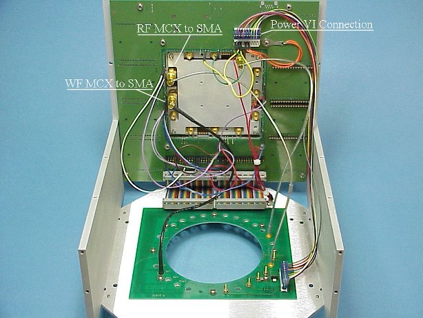 Figure 1.
Cal data has no affect on measured DUT data.
|
- Make sure calibration plan is storing data to the proper calibration factor.
For automated use the path name is case sensitive. It should NOT contain any "F". Only "f" should appear in the path name.
- Make sure calibration plan is resetting the proper calibration factor.
- Make sure the test plan is referencing the proper cal factor.
- Make sure cal data is being saved.
- Spefically on RF4 and RF5 of the Cassini platform. RF4 and RF5 are defined as from the testhead on the RI7100. On the Cassini they need to be defined in the device connection editor as from the tester.
|
S21 Cal Data/Test Data has spikes
in frequency response.
|
- Look for bad grounding or dirty connections/launches. Clean if necessary.
Fixture Cleaning:
Periodic cleaning of the RF connectors and fixture in general is
important. To clean the RF connectors:
- Choose a good quality Q-tip or cotton swab.
- Wet the swab in Isopropyl alcohol 90%. Then place the swab into the connector and twirl it once or twice only.
- Remove any cotton fibers left behind with tweezers or blow them out
with dry air.
- To remove debris from the Teflon insert, use a tooth pick or other sharpened instrument. Carefully wipe the insert being careful not to
put pressure on the center conductor.
- Any dust or debris inside the fixture is best removed by a stream of compressed air.
|
Noisy data at higher frequencies
(repeatable but varies a lot)
|
- Check to make sure test(s) are being done at optimum Receiver IF Gain
levels and power levels.
- Check to make sure the input and output ports are set up properly for the measurement.
- Check the physical RF connections.
|
| Noisy Data - not repeatable |
- Check the physical RF connections.
|
"Float Overflow" at compile
| 
- The test plan being compiled is relying on calibration data that is corrupt.
Make sure that calibration data being invoked is reliable.
|
"Key Is Missing"
|
- Sometimes if cal data is bad, it can cause this error. Please
check the tester/fixture cals to see if there is data in the
fixture that is not good.
- Check to make sure test buttons in test plan match path calls for the tester/fixture. This is especially true of test plans copied from
other devices/fixture types.
|
Software button not working properly Cassini
Example - data not being reset or written over.
|
- When importing a calibration plan used on the RI7100 buttons need to be exchanged for those that work on the Cassini.
EX. Cal Data Reset button or Cal Factor Save Button.
(See Software) |
Modules not controlled
Further Debugging for the smart carrier  |
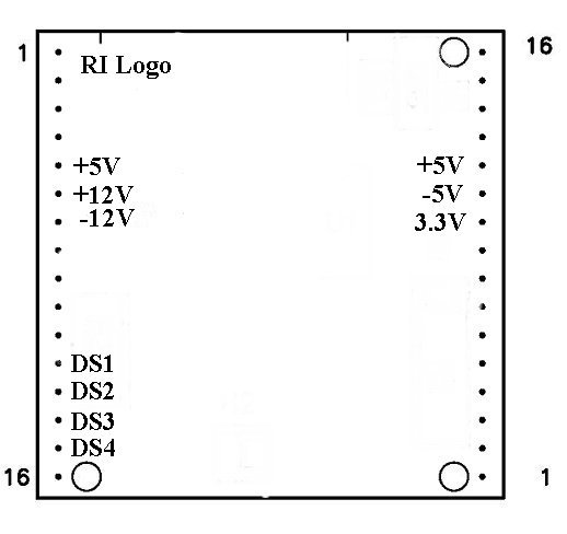
- Establish that proper operating bias is being presented to the module in question. To do this use a volt meter and verify the presence of voltages in accord with Figure 1 below. +3.3V will not be present on the Y0002AC1 carrier board.
- Check the four DS lines (DS1-4) that are used to control module
functions at each module location. These can be controlled from either
the tester controller directly or from a breakpoint in a test plan.
Note: For switch style modules only.
- Make sure the carrier board is configured properly for the module.
(See Modules)
- Make sure the 40 pin ribbon cable is properly seated on the bottom plate and the carrier headers.

- Run diagnostics on the testers Cbits.
|
Will Not Toggle
|
- Make sure you have properly selected the software carrier type for your physical carrier type. A Y0004VA1 carrier will not properly control the
Cbits if it is defined as a Y00065A1. To check what type of carrier you
have:
- highlight the activated fixture and use a RMBC.
- Choose "Inspect" from the pull down menu.
- In the listed attributes on the left hand side of the
inspection window, highlight the term "interface". This will tell
you the software definition of the carrier type.
- If they do not match perform a "Mutate" to the proper fixture type.
A carrier board marked 4VA must show Y0004VA1 A carrier board marked 65A must show Y00065A1
- If you have a Smart Carrier (Y0004VA1 or Y00065A1) the string code for Cbit control is of the format CXY where C is text, Xis the Cbit to be controlled, and Y is either 1 or 0 for state level. Older fixture definitions, copied from a passive carrier, will have to have the Cbit control strings changed to this format. They previously were of the format XXXXXXXX
with each X representing a Cbit state level.
|
| Two device interface files active |
- One file is a copy of the other with both having the same physical
electronic serial number. Move the one not being used to a historical directory. Place the one that is being used into the devices directory under RIAPPS.
|
| Voltages sag or go to 0 V |
- Check module pins and make sure they are not bent.
- Remove modules until voltages go to normal. Fix or replace the offending module.
|
 | |
| Intermittent |
- Check pogo and cable connections for continuity.
|
| Will Not Toggle |
Make sure the program listing in the module browser lists Y12JB13B not Y12JB13A for the RIK0017A. Program number should be Y18NA11A for
the RIK0127A.
Make sure module is in the M1 or M5 position only.
|
| Toggles at 400KHz (SPXP switch) |
- High Speed Digital is being used in M1 or M5 carrier board position. Change switch module position to M2-M4 or M6-M10.
- Remove HS digital instrument from E-Prom if not being used
|
Configuration for the RIK0017A:  Configuration for the RIK0127A:
| Zero value for current |
- Check pogo and cable connections for continuity.
|
General Module Issues
| Modules are dead |
- Make sure that the software fixture is deactivated prior to installation or removal of the physical fixture.
|
| |
Intermittent
|
- Check pogo and cable connections for continuity.
|
Will Not Toggle
|
- Make sure the program listing in the module browser lists Y12JB13B not Y12JB13A for the RIK0017A. Program number should be Y18NA11A for
the RIK0127A.
- Make sure module is in the M1 or M5 position only.
|
Instrument buttons do not appear in editor/controller
|
configuration for the RIK0017A: 
Configuration for the RIK0127A: |
RF Path Loss
| Change in loss abruptly run to run |
- Check and clean the DUT socket.
- Make sure module is seated securely on the carrier board.
|
| RF path loss degradation over time |
- Check RF cables and connectors for breaks.
(See Also RF Path Loss - SPDT and SP4T Switches)
|
| Switch not turned on |
- Make sure module is seated securely on the carrier board.
- Make sure that the fixture power is turned on.
- Make sure that + / -5V appears at the switch pin header (pin 1= -5V and
pin 8 = +5V). For RIK0006B and RIK0026B.
- For RIK0056A, RIK0056B, and RIK0058A.
Establish that proper operating bias is being presented to the module in question. To do this use a volt meter and verify the presence of voltages in accord with Figure 1 below. +3.3V will not be present on the Y0002AC1 carrier board.

- Check the four DS lines (DS1-4) that are used to control module
functions at each module location. These can be controlled from either
the tester controller directly or from a breakpoint in a test plan.
|
| Switch will not toggle |
- Make sure the proper control bit (CBIT) or module control line is being controlled and is in the proper state. The normally closed position is active when the CBIT or control line is high.
- Make sure you have not shorted out, even briefly, the +/-5V supply for the fixture if it is actively controlled (active carrier type).
|
| Toggles at 400KHz |
- High Speed Digital is being used in M1 or M5 carrier board position. Change switch module position to M2-M4 or M6-M10.
- Remove HS digital instrument from E-Prom if not being used.
|
| High path loss when functional |
- Make sure the path has been calibrated properly.
|
| Ripple is very periodic |
- Try measuring at cardinal frequency points (calibration data points). If ripple goes away, increase the number of data points in the associated calibration routine (typically fixture related). This will allow the spline algorithm to work properly.
|
|
Change the receiver filter bandwidth from 7 KHz to 4 MHz to see if this affects the ripple.
|
| Unable to Read |
- Make sure you have a good ground connection between the fixture carrier and the test head. On new new models of the fixture, make sure the grounding strap between the upper and lower halves of the test fixture has been installed.
- Make sure you measure short between the SN line on the carrier and the SN chip on the fixture bottom assembly (RI7100).
- When using the four SN chip board make sure ground (marked) is attached to the proper pin on the 2X5 header.
|
| Reads All 0s |
- Make sure that you measure an open between the SN line and ground. The SN will appear as all 0s when shorted.
|
| General |
- Make sure you have moved/copied the desired fixture to the D:\RIAPPS\fixtures directory (RI7100).
- Make sure the desired DIB is copied into the D:\RIAPPS\device directory (RI7100)
|
| No RiDibCal found for this esn: |
- Typically seen on a Cassini engineering fixture. Remove the SN chip from the back of the carrier.
|
| Unable to Save Test Plan |
- Make sure data save boxes are connected to data outputs.
|
| Test Plan will not compile/run |
- If the test plan was originally written for the RI7100 and you are attempting to use it on Cassini, you may need to replace Ri7100 compatible buttons with Cassini style buttons. (See Calibration)
|
| Test Panel Flags do not work |
- Make sure the flag data has been formatted. Also make sure the limits have been selected. Do not rely on copied buttons during panel creation. Use system copies only (editor).
|
| Shorted or Open |
- Make sure the DIB board clamp is not installed with out the DIB board itself. The clamp will short the pogo pins to ground.
- Make sure the pogo pin pad on the DIB is not shorted to ground.
- Check the pogo pin alignment to make sure that the pogo pin is not shorted
to the fixture top plate.
- Make sure that DC blocks have been provided on the RF pins. A short on an RF pin can draw down a DC pin voltage.
- Make sure the fixture is seated and docked properly on the test head.
- Make sure of continuity between the test head and the carrier board pogo pin. If the pin is attached to a Power VI make sure the cable connections on the
pin headers are installed and aligned properly.
- If the tester has an I_Drive capability (older tester) and the fixture is of new vintage then the I_Drive pin is being grounded by the fixture. Clip Pin#32
on header#1.
- Make sure the 40 pin ribbon cable is properly seated on the bottom plate
and the carrier headers.
- If the above suggestions do not resolve the problem, diagnose the test head
to make sure the resource is working. Make sure that the fixture power is turned on.
|
| Cannot measure correct voltage |
- If the pin is attached to a VCC or Static Digital Pin.
- Suggestion: Make sure the ground reference (GNDREF) and GND are connected to the desired ground.
- If the pin is attached to a Power VI.
- Suggestion: Make sure the VRTNS and RTNS pins are connected to the desired ground.
- If the above suggestions do not work measure the resistance from the
bottom of the fixture to the pogo pin. This should not measure more than about 2 ohms. Reduce the contact resistance if it measures much more
than 3 ohms.
- If the above suggestions do not resolve the problem, diagnose the test head
to make sure the resource is working.
|
Fixture Warnings:
Warning: Once the RF (SSIS to MCX conformable) cables are installed, do not bend the cable within one (1) inch of the pogo circuit board. Bending them at the SSIS connector directly can result in connector damage both on the fixture and on the test head.
Fixture Debug Flow Chart
Published: 08/07/2000 10:45:39 AM Modified: 10/26/2012 04:40:29 PM
https://roos.com/docs/RBEH-73A27L
Roos Instruments CONFIDENTIAL AND PROPRIETARY
©2000-2012 Roos Instruments, Inc. All rights reserved.