

Purpose : To provide examples for Offset creation to aid in DUT Correlation to Engineering Data.
The RI fixturing system not only supports real "physical" calibrations, but also supports arbitrary corrections or "offsets". Physical calibrations are dealt with through pathnames that represent the physical parameters of signal paths in the system. These physical parameters are used in the calibration of the system and power levels and results are modified accordingly.
Arbitrary offsets are sometimes required for correlation. These are not used in the calibration, but just to modify some measured value. Most often these measurement differences are the result of dutboard/dutinterface inconsistencies. These could be tuning or possibly socket related. They can also be the result of differences between the bench measurement environment and the tester measurement environment. A good example might be the time the device is on during bench test versus ATE measurement time.
To deal with this the RI "software" dut interface, can contain user added constants, that can be used to modify measured results. In addition, these constants can be updated automatically with a testplan that measures a "golden" device with known data.
Note: If you are not using a DUT Interface then the user can use the same methodology with the Test Fixture Cal list
I. Create the Cal Factor
The first step in the process is to create a "cal factor" in the software device interface file.
For the RI7100A:
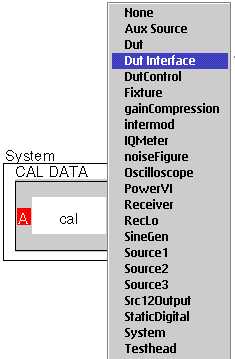
To do this activate the appropriate device interface from the device interface container window. Select Edit and the following screen will appear. In the window we see previously defined "paths" from the fixture connection to the device pin. These paths are part of the device interface calibration and not this exercise. In the lower right section of the dialog box, select the Inspect option

For Cassisni:
Use the Device Connection Editor to add a user Cal Variable to the list of Calibration names associated with that Device Interface Definition. This way the new independent cal variable will be available to all device interface cal files that use this definition.
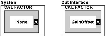
Once you bring up the Cal Table for the device interface, now we will "Add Item" creating the new offset cal factor to use in the testplan. Type the name of the cal factor you wish to create. In this exercise we will call it GainOffset.
Note: No spaces are allowed in the Cal data names.
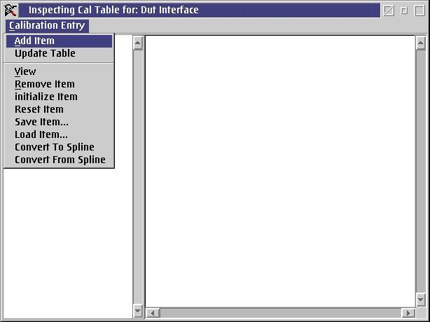
In this case, we are creating a Calibration Entry for GainOffset. Initially the data will be nil . If desired a value can be manually entered. If you want to manually enter a value, after typing in the data, right click and select save. We will be writing a testplan to write the data automatically.

Now that the calibration factor exists in the dutinterface cal table. We can use it in our testplan and our calibration plan for the dut interface.
II. Dut Interface Calibration Plan
To create the calibration plan for the Dut interface we need to have completed our testplan for the part. We will then take that test plan, modify it to compare the measured data with the gold part data, and save the difference into the offset value we just created..
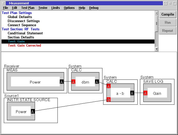
Let us start with our test plan. Here is a simple test plan for a gain measurement.
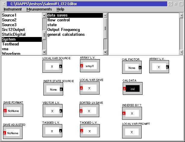
At this point, save the testplan with a different name. In this case it is Cal Dut Interface. We are going to add to this a new button to save the Cal data (offset value).To do this go to the Editor (Tester View) and select System>Data Saves.
That brings up this editor panel. We are going to Select and bring in to our plan the Cal Data button.
We now need to modify this button to make it point to the cal data in the dut interface.
Insert it into the test plan. Then we change it's owner. Do this by placing the mouse just inside the system button, and outside the grey cal button. Right click.
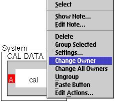
Now that the owner is Dut Interface, select the appropriate cal variable name by placing the mouse in the cal button. Right click and select CalVarName.

Select the Cal Name that we created, GainOffset from the list of active DUT Interface variables.

Now the button is correct.
It is easy to see how the plan can be modified to write the Offset factor into the Dut interface.
1.) The Calc input button is the "gold part data" in this case 10 dB.
2.) Subtract that from the measured value and this becomes the cal data.
Note : You can also enter the data manually into the DUT Interface Cal Variable ( See Manually Inserting Calibration Data in the Dut Interface)
Now the Automatic Calibration Plan is done.
Some notes that apply to all calibration plans:
1) Calibration data is not saved if the testplan is run in Edit Mode!
2) Cal data is saved automatically if the cal plan is run from the Device Interface Calibration Executive. To run it from the Device Interface Calibration Executive it must be in the Device Interface directory under CalTests.
III. Modifying the Measurement Plan to Use the Offset:
Now we need to modify our measurement plan to use the cal factor.
To do this go to the Editor (Tester View) and select System>Data Saves.
Just like the Cal Data Save button, we need to Change the Owner to Dut Interface and Select the Cal variable GainOffset
Now place this in the measurement plan and modify it accordingly.

Several things to note:
1.) Be careful of units. Make sure the measurement is in the correct units before adding/subtracting or even multiplying/dividing by offsets. In this case the gain is in log before I add the offset.
2.) Make sure the polarity of the offset is correct. This can be checked by measuring in the gold part and the gold part gain should equal the corrected gain.
3) This CalTests directory has been changed as of January 2002, patch p21c.085 is required for this to work correctly Contact RI to obtain that patch.
Once a calibration plan has been created, it can be automatically invoked from the Device Interface container window, by a right mouse click and "calibrate". To enable this capability the calibration test plan must located in the correct directory.
1.) Create a directory named for the appropriate Device Interface under riapps\caltests\deviceif\
2.) Place the calibration plan in that directory
3.) From the device interface container window right click and select the calibrate option
You will then see the Device Interface Calibration Executive window. There will be no test plans listed in the upper left window.
4.) From the pull down menus, select testplan>add.
You will get a dialog box with all the device interface types that have calibration folders created. (This is the folder you created under riapps\caltests\deviceif\"your device interface name")
5.) Select the device interface type.
6.) Select the testplan you previously created.
7.) When you close this dialog, it will ask if you want to save changes. Select yes, and the device interface will then always point to that file.
Calibrations can then be automatically run from the dut interface calibration executive window by selecting the desired plan and "run selected"
Attached is a zip archive with the Measurement Test Plan, the CalDutInterface test plan, the Measurement Fixture and the Measurement Device Interface.