
OVERVIEW
This document outlines the advanced conditional calibration, validation and diagnostic verify test plans. The conditional test plans are designed to identify setup errors, prevent damage to the TIM and/or calibration/diagnostic equipment, and provide the user with feedback to correct setup errors.
RI8595 POWER AMPLIFIER: ADVANCED CALIBRATION, VALIDATION, VERIFY
BACKGROUND
Cassini test systems include diagnostic verifies, calibration, and validation test plans for all instruments. As a general principal, diagnostic verifies should be run before calibration and validate test plans to insure that instrument is operational before performing a calibration.
Cassini diagnostics test an instrument’s operational capability. The instrument’s internal components are exercised to detect hardware faults in a controlled test environment, performing various measurements to verify operation, consistency, and repeatability. These tests provide pass or fail results based on factory defined parameters of acceptance. Two modes of evaluation are expressed in the diagnostic tests list available to the user as either ‘diagnose’ or ‘verify’ in the test names. Collectively, both types of tests in the test list are referred to as ‘diagnostics’ on the Cassini test system with the descriptions of each as follows:
- Diagnose tests check fundamental hardware functionality of an instrument’s internal components. A damaged or malfunctioning component will cause the diagnose tests to fail.
- Verify tests check the capability of an instrument to insure that it is compliant with performance specifications of a calibrated instrument. This includes conducting tests to gauge the repeatability of measurements using fixed instrument and I/O port setup conditions in a controlled test environment. In the case of RF instruments, the diagnostics can involve several interconnected instruments. Calibrations quantify intrinsic source and/or measurement error in the form of deviation from standard parameters using traceable reference standards/devices. The measured deviation is used to determine error correction that compensates for this intrinsic error to ensure accuracy and traceability of the instrument. A Cassini instrument calibration consists of a pair or multiple pairs of test plans — a calibration test plan and validation test plan, that are executed in succession.
- Calibration test plan resets internal error correction for a specific reference parameter and performs a comparison of the instrument performance to the calibration reference/s using controlled instrument setups and parameters to ascertain the necessary error correction to attain parity. The measured error correction values are stored in temporary memory. The validation test plan performs a comparison of the instrument performance using the measured error correction values stored in temporary memory with the same calibration references, standards and equipment to quantify the residual error after calibration. The residual error is then limit checked against factory specifications. If the residual error does not meet factory performance specifications, the validation test plan is failed and the error correction is not stored to Guru because it is invalid. Note that the temporary, invalid calibration data remains active in the instrument until it is either physical removed from the test system or a system check is performed. If the residual error meets or exceeds factory performance specifications, the validation test plan is passed and the error correction is stored to Guru as the most recent, valid calibration for the instrument.
- The Validation and calibration test plans are designed to be executed as pairs from the Calibration Executive in order to automate the compile, execution, limit checking, and saving of calibration error correction. As a general principle, the results of a validation test plan are only valid when the validation is executed directly after a calibration has been performed using the identical setup, and reference standards/equipment as the calibration.
EXAMPLES
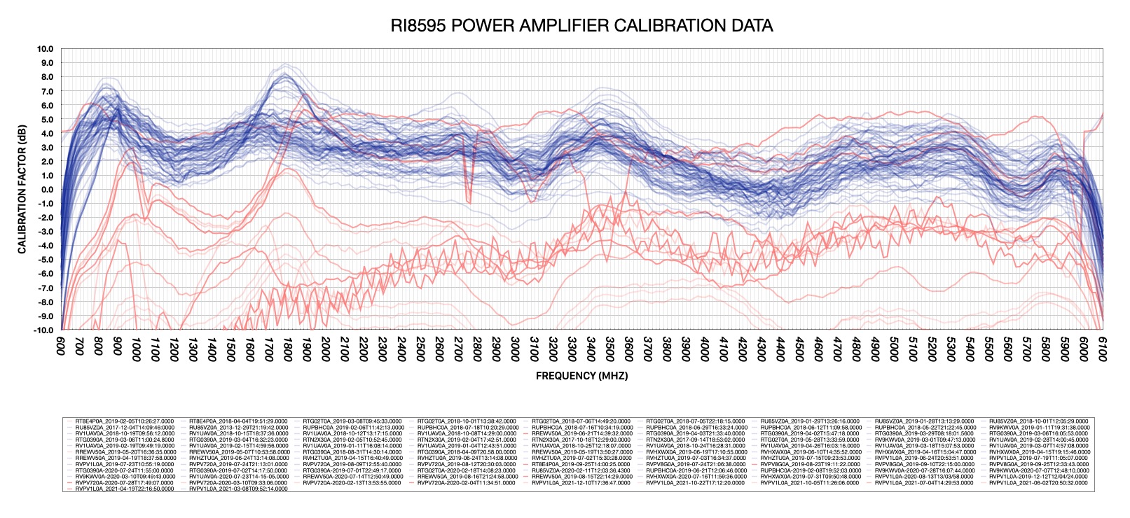
The data shown in Figure 1 is typically expected calibration data (in blue) from 700 MHz to 6 GHz is between 0 dB and 6 dB, but even within that range there is some variability between TIMs due to the variability of the amplifier inside. So the data of a failing RI8595 can be inspected for unusual characteristics: spikes, suck outs, ripple, and/or values outside the nominal range.
For instance, you can see some outlier calibration data (in red) representing either TIMs that are damaged (values less than 0 dB between 700 MHz to 6 GHz) or incorrect calibration results (spikes, suck outs, and excessive ripple).
RI developed advanced RI8595 power amplifier diagnostic and calibration/validation test plans first deployed in January 2024.
Figure 1: Plot comparing calibration data for 15 different RI8595 TIMs between 2018 and 2021: