

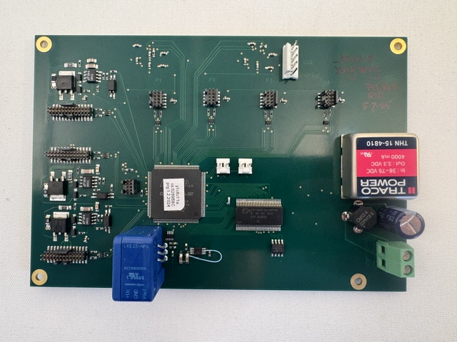
The Cassini 16 Infrastructure's Testhead uses a stack of three PCBs as the RIFL Hub (RIFL main board) to distribute power and control to the Front and Rear RIFL top boards and the four RIFL II "H-location" ports used for controlling AUX instruments and handler/prober. These instructions detail how to remove the access panel and replace the RIFL Hub. The RIFL Hub is secured notched nuts to the Test Head with 4 (four) RIFL II ports. Contact Support ([email protected]) for specific instructions for diagnosing or replacing malfunctioning items.
Replacement Hardware:
Y000C8D1 Cassini 8 RIFL Master
Additional Tools Needed:
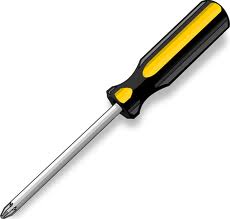
#1 Philips Screwdriver (Panels)
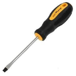
#1 Flat Head Screwdriver (Power Supply)
Electrical Shock Hazards
There are NO electrical shock hazards from any of the exposed electrical connections on the test head or on any surface of the system. The system uses 48 volts or less and shock hazards are typically designated as to 50 volts or higher. No high-voltage cables or connections are exposed at any time during operations or when moving the system. Fixtures and Tester Instrument Modules (TIMs) can be safely removed "hot" without disconnecting power without damaging the equipment or exposing live connections to the operator.
Spyder RIFL Hub Removal
- IMPORTANT: Unplug the 48V DC Adapter from the Infrastructure.
- Rotate the top of the Testhead away (as pictured). Diagram A shows the ## screw locations needed to remove the access panels for either the Testhead.
<SPYDER HEAD DIAGRAM NEEDED>
- Unscrew the Ground Cable from the mounting block. Use a flat head screwdriver to loosen the power cables. Unplug the 5 ribbon cables.
TODO: UPDATED DIAGRAM OR PICTURES
- TODO Describe each header removed.
To install, reverse the process as follows:
- Plug in the power cables into correct location (red to 48v and black to BLK)and secure with flat head screwdriver. Attach ground cable to the top most mount hole and reconnect all 5 flat ribbon cables (note: a header is left empty between C3 and C2). The ribbon cable's header connection is keyed to provide correct orientation. Do not change the ribbon cable locations or bends in the cable.
- Carefully re-install the side panel.
- Connect Power to the Infrastructure.
- Plug the TIMs back in, power ON and follow the steps to run system Diagnostics.